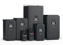
Mini Vector Inverter/VFD ;AC Inverter special for CNC machinet tool 4KW,3ph,380V, 50Hz
| 45 days Money back Returns accepted if product not as described, buyer pays return shipping; or keep the product & agree refund with seller. | |
|
On-time Delivery Guarantees: On-time Delivery 60 days |
Most Popular from Category
The features of the Mini Vector Inverter/VFD GD20 Series are as follows:
① New structure design
1. Mini design, smaller installation space;
2. Compatible with rail and wall installation, flexible installation manner;
3. Available multi-inverter in parallel installation, more effective space-saving.
② Easy maintenance
1. External keypad;
The standard membrane keypad supports external LED keypad and facilitates on-site applications; support external LED keypad with parameter copying, the two-keypad operating functions are convenient for commissioning control;
2. Swapple cooling fan, easy maintenance.
③ Reliable QA
1. The product design strictly follows IEC international standards and passes the CE test;
2. Advanced thermal technology makes exact thermal design.
④ Excellent performance
1. Excellent vector control performance;
Current waveforms in vector control mode with 50Hz and full load.
2. Excellent motor drive performance;
| Current waveforms when sudden loading in V/F control mode with 2Hz and full load | Current waveforms when sudden unloading in V/F control mode with 2Hz and full load |
| Current waveforms when sudden loading in vector control mode with 0.5Hz and full load | Current waveforms when sudden unloading in vector control mode with 0.5Hz and full load |
3. Excellent high frequency running performance;
| Current waveforms when stably running in vector control mode with 400Hz | Current waveforms when stably running in vector control mode with 200Hz |
⑤ Multi-function and easy to use
| Name | Function | Illustration |
| 485 communication interface | Connect with upper computer, read and modify parameters of the inverter, control running states of the inverter | Standard built-in 485 communication interface |
| PID | Carry out PID operation on feedback signals, control output frequency of the inverter and improve target accuracy and stability; apply to pressure, flow and temperature process control | Support PID output polarity switching |
| Motor autotuning | Carry out rotation or static autotuning, improve control accuracy and response speed | Include rotation autotuning and static autotuning |
| Simple PLC | Can change the running frequency and direction automatically according to the running time set by simple PLC to meet process requirements | Support multiple running modes |
| Multi-step speed control | Can meet the requirements of speed control in different periods of time via multi-step speed control | Max. available 16-step speed control |
| Multiple V/F curve settings | Meet the requirements of fans and water pumps in energy-saving operation and various variable frequency power supplies, adapt to different load applications | Linear, multi-dot, multi-power and V/F separation settings, realize flexible setting of V/F curves |
| Virtual terminals | Can take external signals as local virtual I/O to save hardware configuration | Enable the corresponding virtual terminal functions in communication mode |
|
Delay switching on and off |
Provide more programming and control modes |
Max. switching on-off delay is 50s |
| Continuous running in instantaneous power off | Specially apply to the situations with high requirement of continuous operation, ensure the device does not stop in instantaneous power off | At transient voltage drop, the inverter can keep running by feedback energy without stop in valid time |
| Various protection functions | Provide overall fault protection functions | Protection functions such as overcurrent, overvoltage, undervoltage, overheating, overload, can save fault information |
| Optional braking modes | Provide multiple braking modes, satisfy accurate and quick stop under different loads | DC braking, flux braking, short-circuit braking |
| Battery capacity display | Can display the accumulative power consumption on the inverter in no need of watt-hour meter | Can check power consumption of the inverter |
|
Model |
Voltage class |
Output power (kW) |
Input current (A) |
Output current (A) |
STO function |
|---|---|---|---|---|---|
|
GD20-0R4G-S2-EU |
1PH220V |
0.4 |
6.5 |
2.5 |
Class SIL2 PLd CAT.3 |
|
GD20-0R7G-S2-EU |
0.75 |
9.3 |
4.2 |
||
|
GD20-1R5G-S2-EU |
1.5 |
15.7 |
7.5 |
||
|
GD20-2R2G-S2-EU |
2.2 |
24 |
10 |
||
|
GD20-0R4G-2-EU |
3PH220V |
0.4 |
3.7 |
2.5 |
Class SIL2 PLd CAT.3 |
|
GD20-0R7G-2-EU |
0.75 |
5 |
4.2 |
||
|
GD20-1R5G-2-EU |
1.5 |
7.7 |
7.5 |
Class SIL3 PLe CAT.3 |
|
|
GD20-2R2G-2-EU |
2.2 |
11 |
10 |
||
|
GD20-004G-2-EU |
4 |
17 |
16 |
||
|
GD20-5R5G-2-EU |
5.5 |
21 |
20 |
||
|
GD20-7R5G-2-EU |
7.5 |
31 |
30 |
||
|
GD20-0R7G-4-EU |
3PH380V |
0.75 |
3.4 |
2.5 |
Class SIL2 PLd CAT.3 |
|
GD20-1R5G-4-EU |
1.5 |
5.0 |
4.2 |
||
|
GD20-2R2G-4-EU |
2.2 |
5.8 |
5.5 |
||
|
GD20-004G-4-EU |
4 |
13.5 |
9.5 |
Class SIL3 PLe CAT.3 |
|
|
GD20-5R5G-4-EU |
5.5 |
19.5 |
14 |
||
|
GD20-7R5G-4-EU |
7.5 |
25 |
18.5 |
||
|
GD20-011G-4-EU |
11 |
32 |
25 |
||
|
GD20-015G-4-EU |
15 |
40 |
32 |
||
|
GD20-018G-4-EU |
18.5 |
47 |
38 |
||
|
GD20-022G-4-EU |
22 |
51 |
45 |
||
|
GD20-030G-4-EU |
30 |
70 |
60 |
||
|
GD20-037G-4-EU |
37 |
80 |
75 |
||
|
GD20-045G-4-EU |
45 |
98 |
92 |
||
|
GD20-045G-4-B-EU |
45 |
98 |
92 |
||
|
GD20-055G-4-EU |
55 |
128 |
115 |
||
|
GD20-055G-4-B-EU |
55 |
128 |
115 |
||
|
GD20-075G-4-EU |
75 |
139 |
150 |
||
|
GD20-075G-4-B-EU |
75 |
139 |
150 |
||
|
GD20-090G-4-EU |
90 |
168 |
180 |
||
|
GD20-090G-4-B-EU |
90 |
168 |
180 |
||
|
GD20-110G-4-EU |
110 |
201 |
215 |
||
|
GD20-110G-4-B-EU |
110 |
201 |
215 |
Wiring diagram of control circuit Control terminal diagram Connection terminal diagram for inverters ≤2.2kW Connection terminal diagram for inverters ≥ 4kW Function description of control terminal
|
Item |
Terminal symbol |
Terminal name |
Terminal function |
|
Analog output |
AO1-GND |
Analog output 1 |
1. Output range: 0~10V voltage or 0~20mA current; 2. Voltage or current output is set by jumpers or toggle switch; 3. Error ±1%, 25°C; 4. There is only one AO1 for inverters ≤ 2.2kW. |
|
AO2-GND |
Analog output 2 |
||
|
Digital output |
Y1-COM |
Digital output |
1. Contact capacity: 50mA/30V; 2. Output frequency range: 0~1KHz; 3. Default is STO state output indicator. |
|
STO function input |
24V-H1 |
STO input 1 |
1. Safety torque stop (STO) redundant input, externally connected to NC contact, STO acts when the contact is open, and the drive stops output; 2. The safe input signal cable should be shield cable within 25m. 3. When employing STO function, please disassemble the short circuit plate on the terminals shown in fig 3.10 and fig 3.11. |
|
24V-H2 |
STO input 2 |
||
|
Relay output |
RO1A |
NO contact of relay 1 |
1. Contact capacity: 3A/AC250V, 1A/DC30V; 2. Please note that it should not be used as high frequency switch output; 3. There is only one relay output for inverters ≤2.2kW. |
|
RO1B |
NC contact of relay 1 |
||
|
RO1C |
Common terminal of relay 1 |
||
|
RO2A |
NO contact of relay 2 |
||
|
RO2B |
NC contact of relay 2 |
||
|
RO2C |
Common terminal of relay 2 |
Function parameter table Newly added function codes are listed as below:
|
Function code |
Name |
Instruction |
Default value |
Modify |
|---|---|---|---|---|
|
P06.01 |
Y1 output selection |
0: Invalid 1: In operation …… 25: Reserved 26: DC bus voltage build-up is completed 27: STO action 28~30: Reserved |
27 |
○ |
|
P06.03 |
Relay RO1 output selection |
1 |
○ |
|
|
P06.04 |
Relay RO2 output selection |
5 |
○ |
|
|
P07.27 |
Current fault type |
0: No fault 1: Inverter unit U phase protection (OUt1) …… 35: Maladjustment fault (STo) 36: Underload fault (LL) 37: Safety torque stop (STO) 38: Channel 1 is abnormal (STL1) 39: Channel 2 is abnormal (STL2) 40: Channel H1 and H2 become abnormal simultaneously (STL3) 41: Safety code FLASH CRC check fault (CrCE) |
● |
|
|
P07.28 |
Type of the previous one fault |
● |
||
|
P07.29 |
Type of the previous two faults |
● |
||
|
P07.30 |
Type of the previous three faults |
● |
||
|
P07.31 |
Type of the previous four faults |
● |
||
|
P07.32 |
Type of the previous five faults |
● |
||
|
P11.16 |
Extension function selection |
0x000~0x111 LED ones: Automatic frequency downgrade at voltage drop 0: Automatic frequency downgrade at voltage drop is invalid 1: Automatic frequency downgrade at voltage drop is valid LED tens: The second ACC/DEC time selection 0: The second ACC/DEC time detection selection is invalid 1: The second ACC/DEC time detection selection is valid, |
0x000 |
○ |
|
when the operation is above P08.36, ACC/DEC time is switched to the second ACC/DEC time LED hundreds: STO function selection 0: STO alarm locked Alarm lock means when STO appears, reset is a must after state recovery. 1: STO alarm unlocked STO alarm unlocked means when STO appears, STO alarm will disappeare automatically after state rescovery. Note: STL1~STL3 are fault lock and cannot be reset |
Fault Instruction for newly added fault codes:
|
Fault code |
Name |
Instruction |
|
STO |
Safe torque off |
STO function operates normally |
|
STL1 |
Channel H1 abnormal |
Fault or internal hardware circuit fault occurred to H1 channel |
|
STL2 |
Channel H2 abnormal |
Fault or internal hardware circuit fault occurred to H2 channel |
|
STL3 |
Channel H1 and H2 abnormal simultaneously |
Fault or internal hardware circuit fault occurred to H1 and H2 channels simultaneously |
|
CrCE |
Safe code FLASH CRC check fault |
Error occurred to STO safe code FLASH CRC check |
STO alarm 1) When the hundreds of P11.16 is set to 1, the STO alarm is locked As shown in below fig 1, When H1 and H2 are ‘OFF’ during operation (safety function is required), the drive enters safety mode and stops output. STO alarm will only be disappeared once reset action is valid. External running command need to be reset for the drive to execute running command again. Fig 1 2) When the hundreds of P11.16 is set to 2, the STO alarm will not be locked As shown in below fig 2, alarm non-lock means when STO appears, the STO alarm will disappear automatically after state restoration, which requires no reset action. After reset of external running command, the drive will execute running command again. Fig 2 STL1 fault As shown in below fig 3, when the hardware circuit of safety circuit 1 is abnormal while that of H2 signal is normal, namely, when H1 is abnormal during operation (safety function is required), the drive enters safety mode and stops output no matter whatever the running command is. Despite of reset commands and external running command reset, the drive will not execute running command again, and it is STL1 alarm lock all the time. Fig 3 STL 2 fault As shown in below fig 4, when the hardware circuit of safety circuit 2 is abnormal while that of H1 signal is normal, namely, when H2 is abnormal during operation (safety function is required), the drive enters safety mode and stops output no matter whatever the running command is. Despite of reset commands and external running command reset, the drive will not execute running command again, and it is STL2 alarm lock all the time. Fig 4
| Function | Specification | |
| Power input | Input voltage (V) | 1PH 220V (-15%)~240V(+10%) 3PH 380V (-15%)~440V(+10%) |
| Input current (A) | Refer to the rated value | |
| Input frequency (Hz) | 50Hz or 60Hz, allowed range: 47~63Hz | |
| Power output | Output motor capacity (kW) | Refer to the rated value |
| Output current (A) | Refer to the rated value | |
| Output voltage (V) | =input voltage, error<5% | |
| Technical control feature | Control mode | SVPWM, SVC |
| Adjustable-speed ratio | 1:100 | |
| Speed control accuracy | ±0.2% (SVC) | |
| Speed fluctuation | ± 0.3% ( SVC) | |
| Torque response | <20ms (SVC) | |
| Torque control accuracy | 10% | |
| Starting torque | 0. 5Hz/150% ( SVC) | |
| Overload capability | 150% of rated current: 1 minute 180% of rated current: 10 seconds 200% of rated current: 1 second |
|
| Running control feature | Frequency setting method | Digital setting, analog setting, pulse frequency setting, multi-step speed running setting, simple PLC setting, PID setting, MODBUS communication setting Shift between the set combination and set channel. |
| Auto-adjustment of the voltage | Keep a stable voltage automatically when the grid voltage transients | |
| Fault protection | Provide comprehensive fault protection functions: overcurrent, overvoltage, undervoltage, overheating, phase loss and overload, etc. | |
| Peripheral interface | Analog input | 1 (AI2) 0~10V/0~20mA and 1 (AI3) -10~10V |
| Analog output | 2 (AO1, AO2) 0~10V/0~20mA | |
| Digital input | 4 common inputs, the Max. frequency: 1kHz; 1 high speed input, the Max. frequency: 50kHz |
|
| Digital output | 1 Y1 terminal output; 2 programmable relay outputs | |
| Relay output | 2 programmable relay outputs RO1A NO, RO1B NC, RO1C common terminal RO2A NO, RO2B NC, RO2C common terminal Contact capacity: 3A/AC250V |
|
| Others | Mountable method | Wall and rail mountable |
| Braking unit | Embedded | |
| EMI filter | Optional filter: meet the degree requirement of IEC61800-3 C2, IEC61800-3 C3 | |
| Temperature of the running environment | -10~50°C, derate above 40°C | |
| Altitude | <1000m If the sea level is above 1000m, please derate 1% for every additional 100m. |
|
| Protective degree | IP20 | |
| Safety | Meet the requirement of CE | |
| Cooling | Air-cooling | |
0 out of 5 (0 Ratings)
| Positive (0%) |
5 Stars (0)
|
|
4 Stars (0)
|
|
| Neutral (0%) |
3 Stars (0)
|
| Neutral (0%) |
2 Stars (0)
|
|
1 Star (0)
|
| Name | Rating | Feedback |
|---|
| Shipping Company | Shipping Cost | Estimated Delivery Time |
|---|---|---|
| 3 - 7 days | ||
| 3 - 7 days | ||
| 5 - 14 days | ||
| Post Air Mail | Free Shipping | 15 - 45 days |
| Return Policy | If the product you receive is not as described or low quality, the seller promises that you may return it before order completion (when you click "Confirm Order Received" or exceed confirmation timeframe) and receive a full refund. The return shipping fee will be paid by you. Or, you can choose to keep the product and agree the refund amount directly with the seller. N.B.: If the seller provides the "Longer Protection" service on this product, you may ask for refund up to 15 days after order completion. |
|---|---|
| Seller Service | On-time DeliveryIf you do not receive your purchase within 60 days, you can ask for a full refund before order completion (when you click "Confirm Order Received" or exceed confirmation timeframe). |


Most Popular from Category

Word’s smallest barcode reader engine integrated into Tablet PC and smartphone

iphone eeprom repair machine for iPhone 4s 5 5c 5s 6 6s plus chip error repair tool and hardware icloud remove

IPAD mini2 HDD disk NAND fixture repair tool for refresh the system NAND and re-write SN data recovery with directly assembly
PCIE iphone7 7P 6s 6sp ipad pro NAND Flash iphone Repair HDD Serial Number SN Tool Test Fixture Expand the nand capacity

Numerical Control Machine Tool Use Three-phase Stepper motor 130BYG350E-X60(N.M)

FANUC cnc spare part pcb circuit board machine tool kits A16B-3200-0290.
online shopping, buying directly from manufacturers?
- Go to Alibaba.com and enter the wanted item into search field.
- Having made your choice, click "Contact supplier" button on the right
- On the next page enter your request and click "Send" button.
- Upon clicking you will be asked to get registered. Do it and wait for the reply.
 ▼
▼